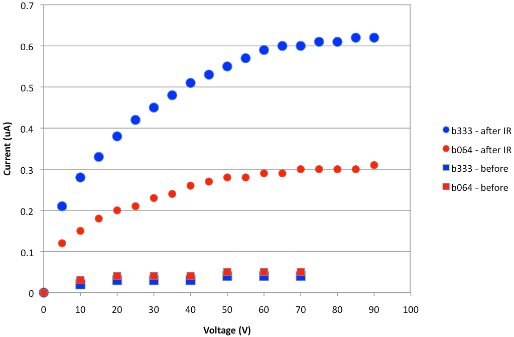
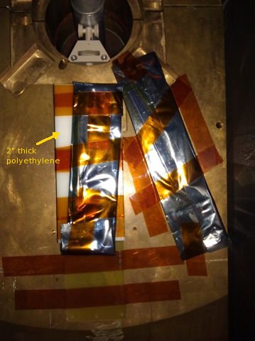
The wedge taped to the brass is placed such that
the tip is at the same radial distance as the other one, and pointing to the
beam pipe. This envelope also holds a TLD, taped to the approximate cented
of the wedge. A TLD from the same batch (dated
2006) is kept in 510.
Wedges were mounted Wednesday 14 March 2012 at about 16:00, and dismounted
20 Mar 2012, about 08:00.
Similar photos taken just before removal: DSCN4706.JPG, DSCN4707.JPG DSCN4708.JPG
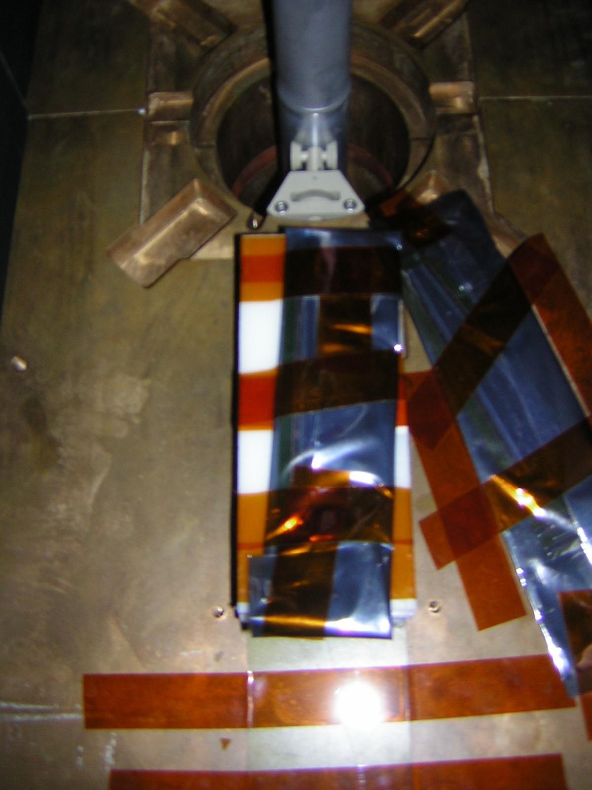
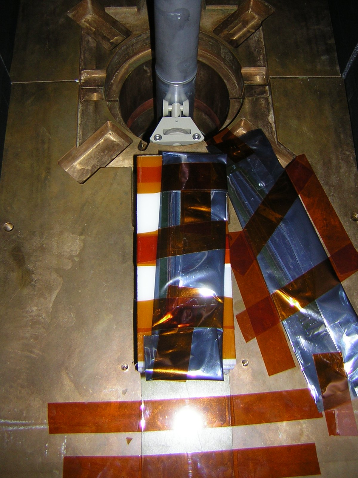
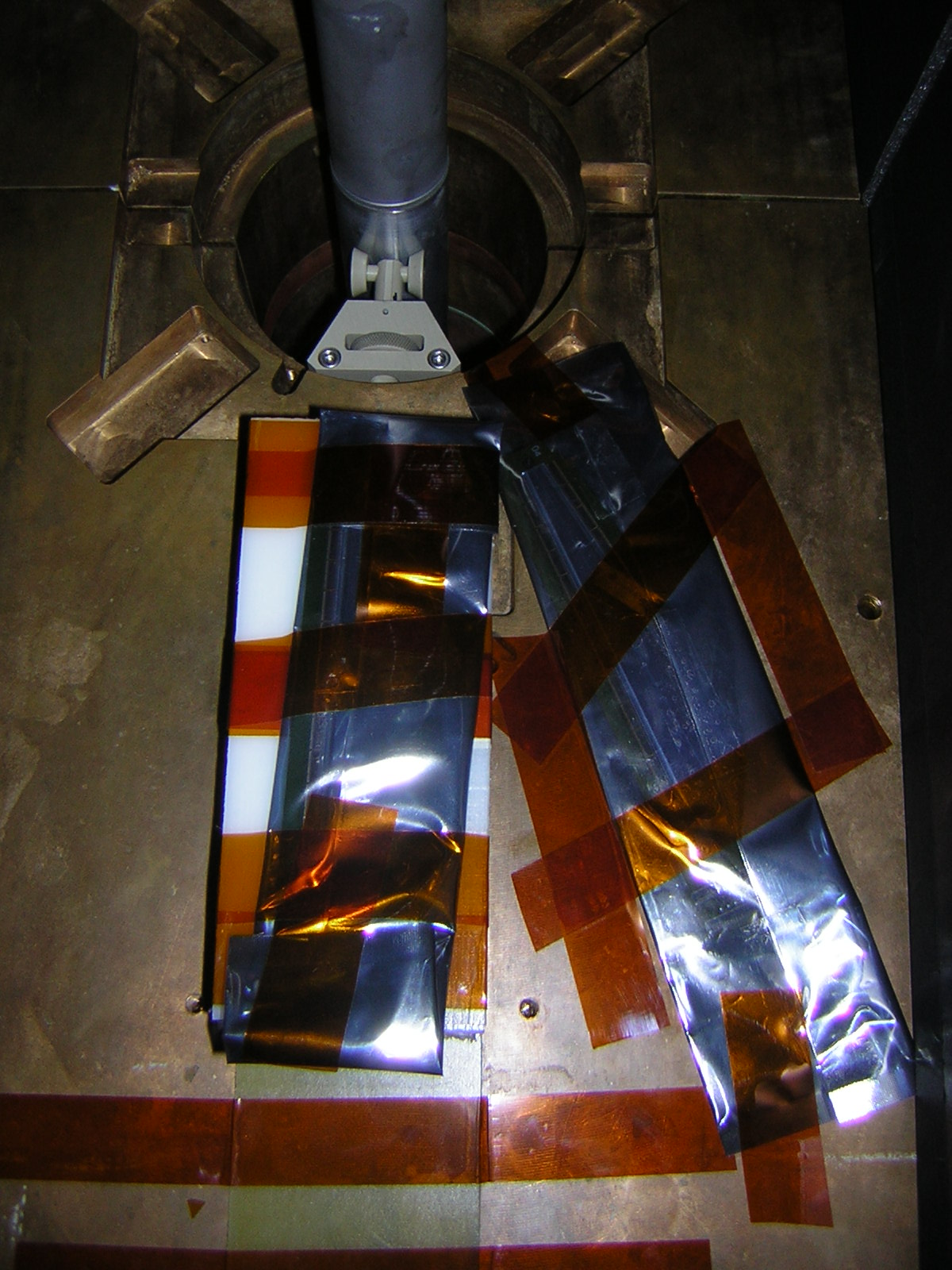
Some more pictures: DSCN4712.JPG, DSCN4713.JPG

References to the radiation issue:
- FVTX elog entries 3329, 3330, 3339,
- (email 20 Mar) Based on the test wedges, estimate of the fluence on our detector
- (email 09 Mar) Ming's updated presentation, and slides
- (email 12 Mar) John Koster's VTX bias current studies, and John's presentation 3 March, and
- (email 12 Mar) expected 10-year fluxes
- (email 12 Mar) Slow neutrons and polyethylene
- (email 14 Mar) Particle spectrum at MuTr station1, and a link to Itaru's pdf
- (email 14 Mar) About CDF rad study, and the CDF study pdf
- Studies of the nosecone and neutron shielding
- Phenix projected radiation dose study, 2007
- (F)VTX actual dose study, 2012
- NIM A315 (156) 1992: Study of the effects of neutronirradiation on strip detectors
- Radiation damage studies for the VTX
- Oleg's Eyser's study of neutrons for the MPC
- A thesis on radiation damage (Hurley, UC Santa Cruz)
- Slide on shot noise (vs leakage current)
- Eric's link list on the ATLAS Medpix device