There are a few locations where the cooling channel milled into the peek edge of the support disk core comes close to the outside. If these locations fail an over-pressure leak test, can these situations be improved?
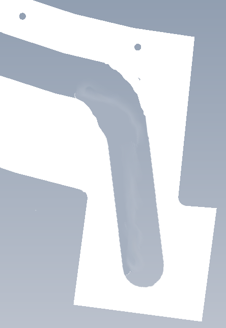
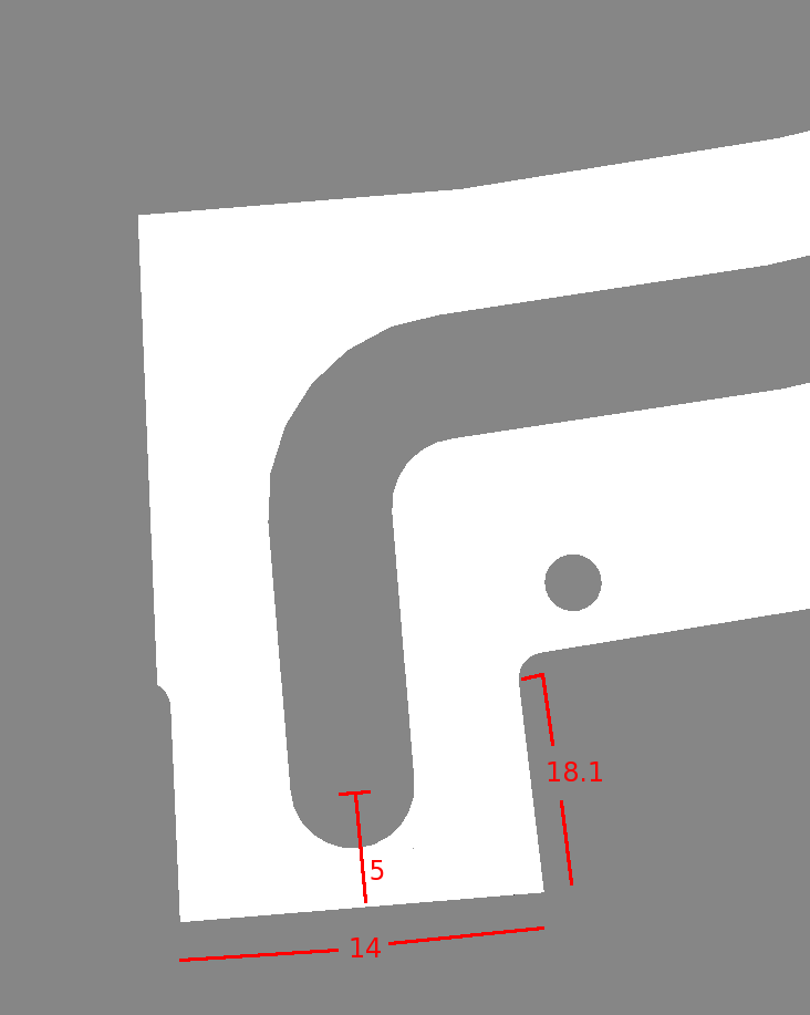
| (1) Station entry channel at the bottom. There is a narrow wall in this area (arrow). The channel runs between the edge and a hole. What is this hole? Fig. 1 | 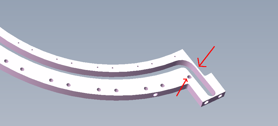
|
| This hole is for a screw that holds down the foot of the first
module on the front. If we eliminate this hole, we can move the channel over,
and then we would have to mount this module-1 foot with thermally
conducting glue. This means that replacing this one module - if needed -
would be a bit more difficult.
Fig. 2 | 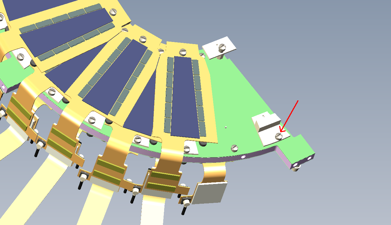
|
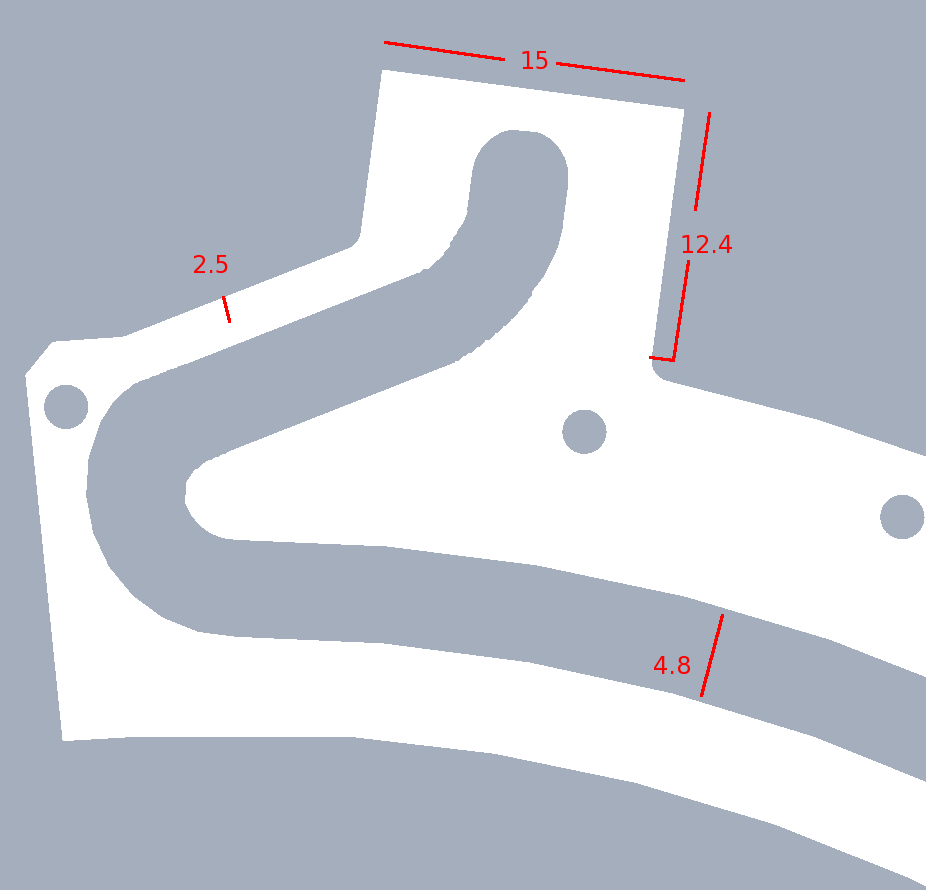
| A bracket around this weak spot would push the disks apart, unless
we file off some carbon/peek on the opposite side.
Fig. 3 | 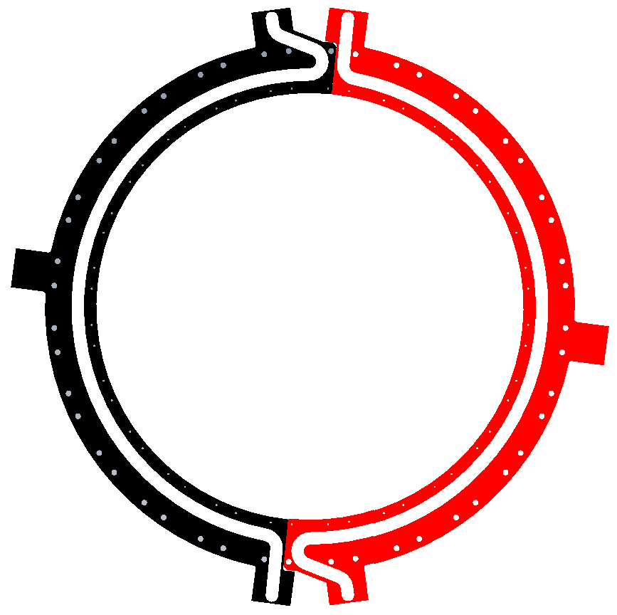
|
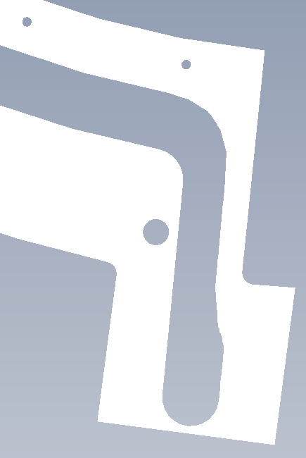
| If we can rework this sregion, we should move the hosebarb up,
abandon the screw hole of the 1st module, and angle the channel away from
the center plane (in this drawing up by 2mm, and rotated by 12°).
Fig. 4,5 | 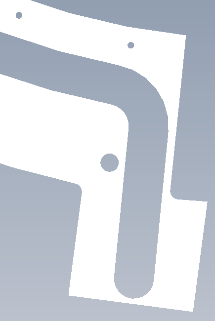
|
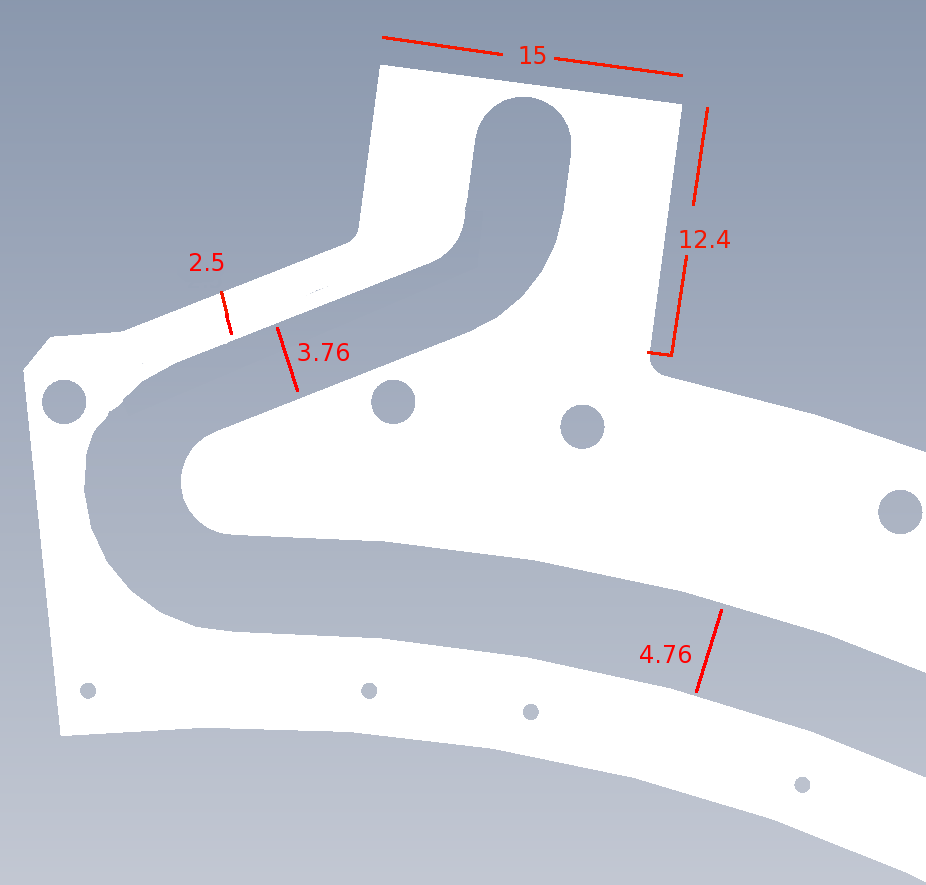
| We can't abandon any holes, since the carbon cover sheets are
already made, and already have holes in those locations. However, the cooling
requirements for Station 1 are 10/26th of the big disk requirements, and the
travel distance of the heat is shorter, so we can make portions of the
channel narrower. Since the flow is turbulent, the flow rate scales with
channel cross section.
Fig. 4a,5a |
|
| (2) Station 1 top hose connection The hose barbs are placed very close to the edge of the top and bottom mounting tabs, as can be seen here. The screw and the pin go to the half-cage. This hose barb location can be moved down - there are no cables in the way. Fig. 6 | 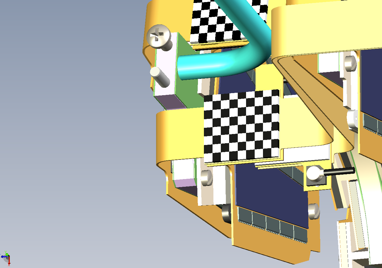
|
| Station 1 top - detail. The hose connection can be moved down
by 9.29 mm before hitting the foot of the second module on the back side.
Fig. 7 | 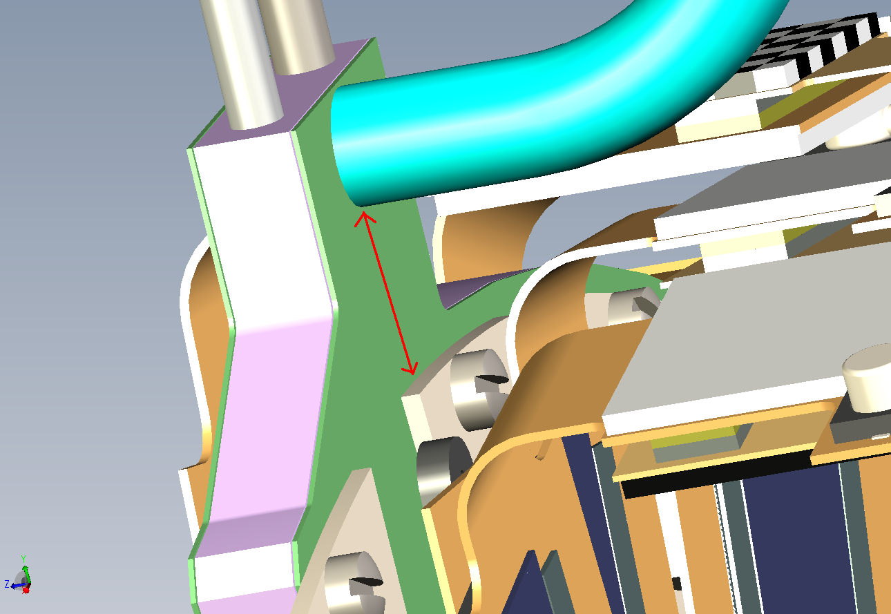
|
| Station 1 top - new peek. Before (left) and after (right). Note here
another screw hole has been abandoned.
Fig. 8,9 | 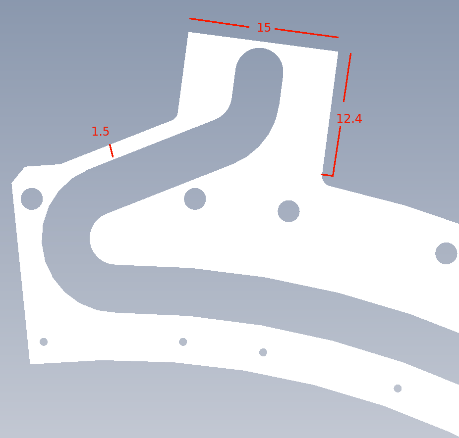
|
| Same here - we can't abandon holes. In the modification of fig 9b,
a portion of the channel is now narrower.
Fig. 8a,9a |
|
| (3) Station 1 bottom hose connection This connection can be moved up. Fig. 10 | 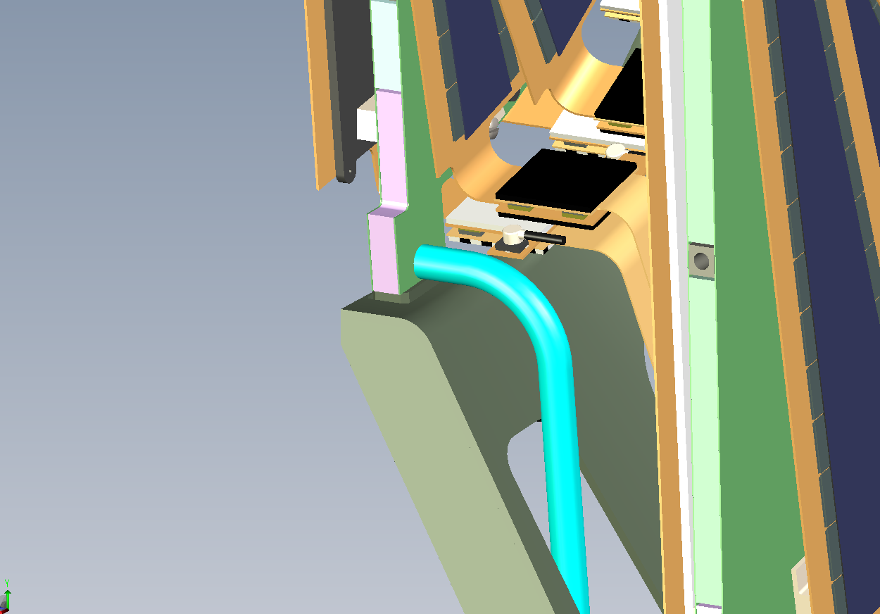
|
| Station 1 bottom - detail.
If you move the connection up by 3.2 mm, it ends up in the middle of the 'square tab' of the disk. Fig. 11 | 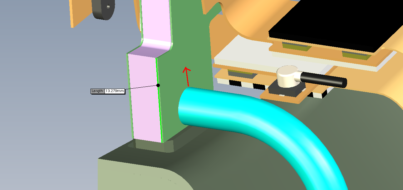
|
| (4) Stations 2,3,4 top hose connections These connections can be moved down. The situation is identical for each of these stations Fig. 12 | 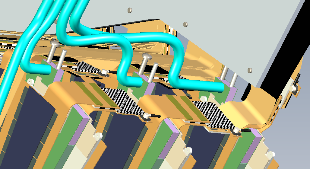
|
| Stations 2,3,4 top - detail
If you move the hose barb down by 3.45 mm, the hose (not shown) will almost touch the white foot of the module. Fig. 13 | 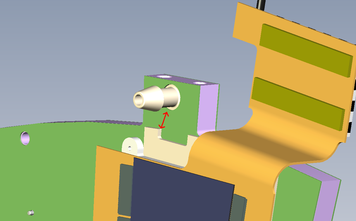
|
| Stations 2,3,4 top - new peek
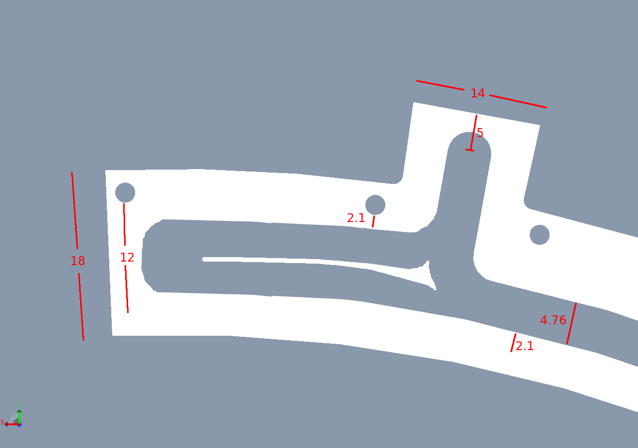
If you move the hose barb down by 2 mm, you get sufficient space on the top of the inlet. While we're at it, I would mill a channel to the left with a thin wall in the middle. This will get at least some circulation towards the first module. Fig. 14,15 | 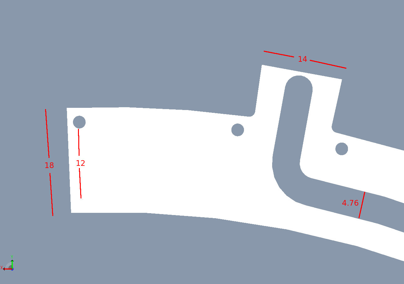
|
| (5) Stations 2,3,4 bottom hose connections. These connections can be moved up. Fig. 16 | 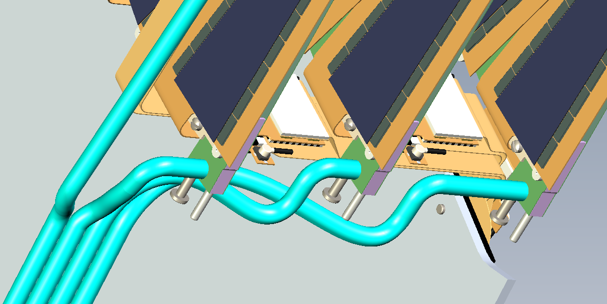
|
| Stations 2,3,4 bottom - detail.
The hose barb can move up by 5.26 mm before hitting the half-round ground tab of the carbon wedge. Fig. 17 | 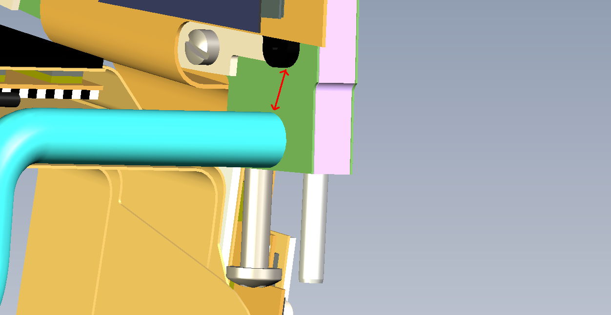
|
| Stations 2,3,4 top - new peek
If you move the hose barb up by 2 mm, you get sufficient space on the bottom of the inlet. Fig. 18,19 | 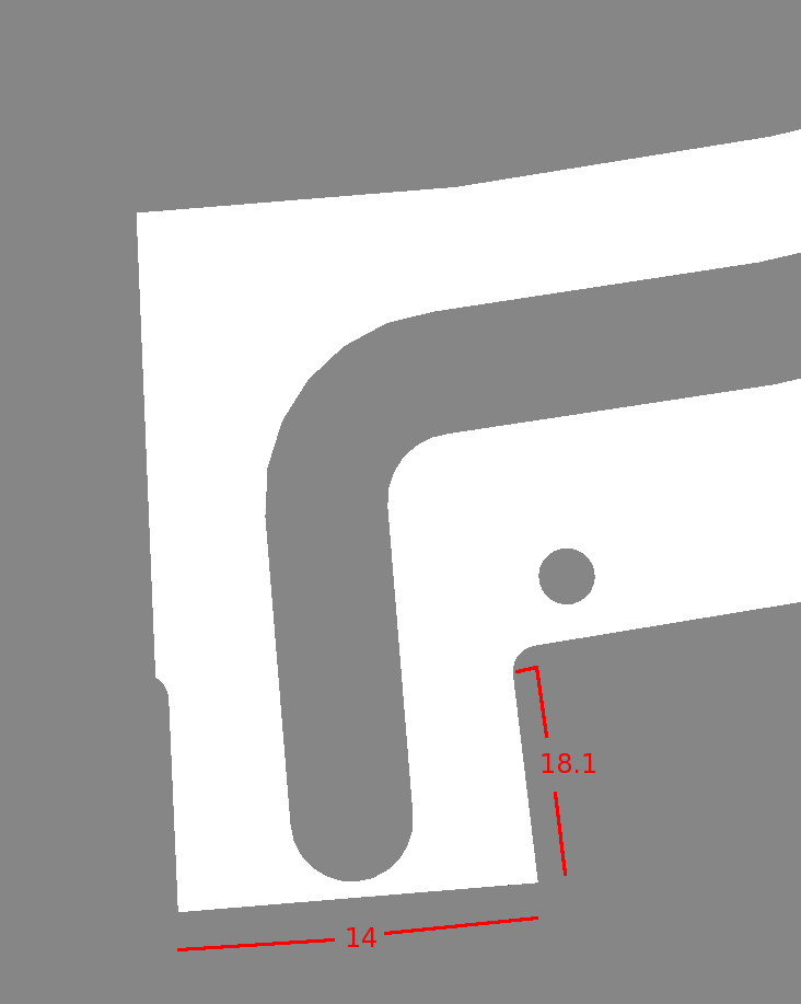
|
Hubert van Hecke Last modified: Fri Oct 22 15:46:47 MDT 2010