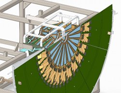
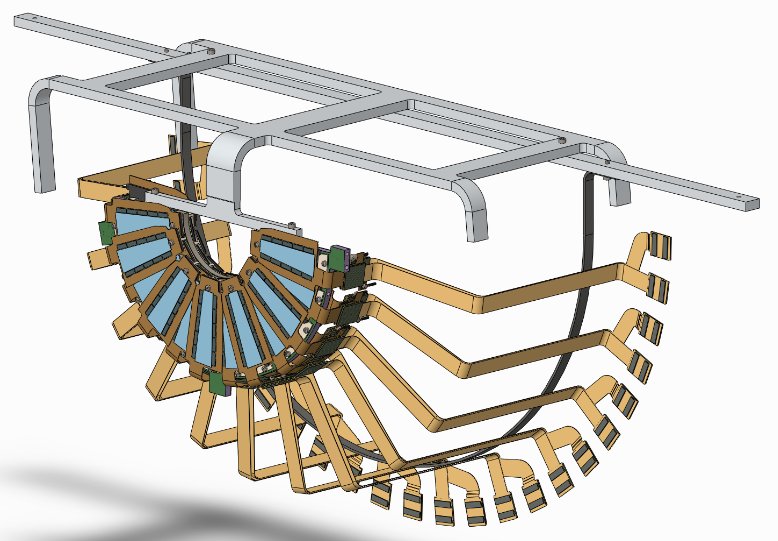
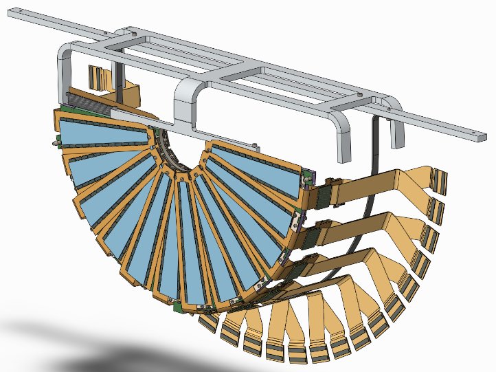
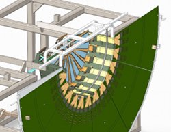
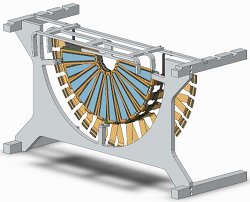
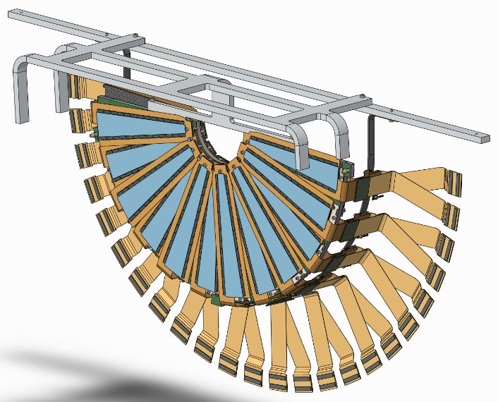
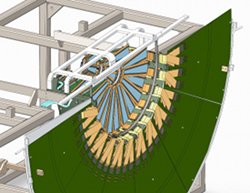
Note the arc that supports the extension cables. The cables are tied to this arc with thread.
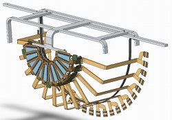
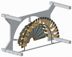
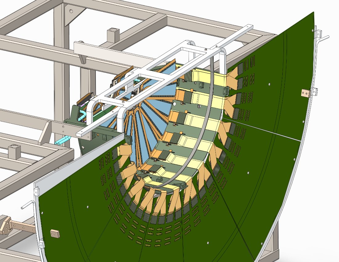
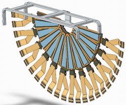
Sheets can be attached to the exterior of this fixture, turning it into a storage and transportation box. FVTX top is on the left in this picture for the NW and SE quarters.

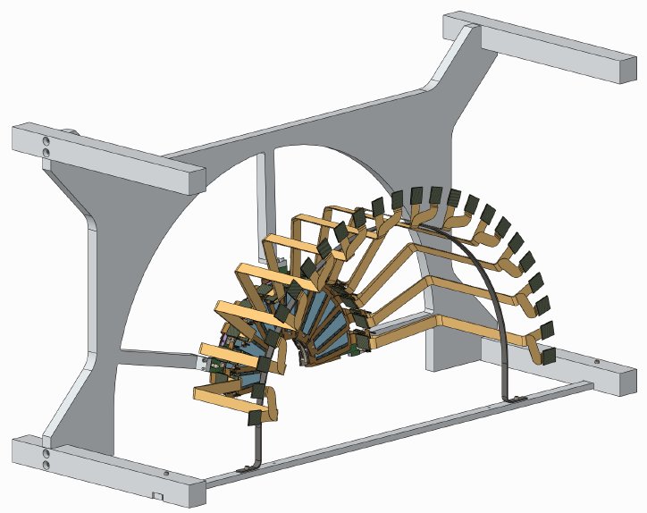
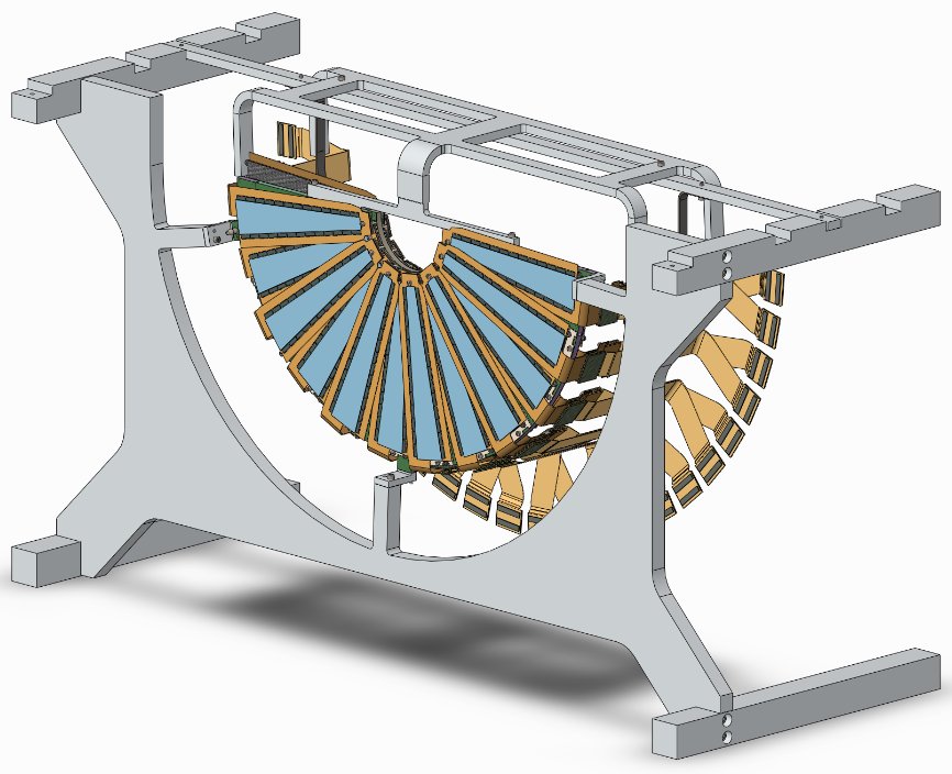
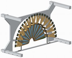
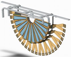
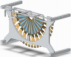
The assembly has been turned upside down, and a lifting fixture has been attached that captures the edge of the disk, as well as the arc holding the cables. Note the four unequal-length legs.
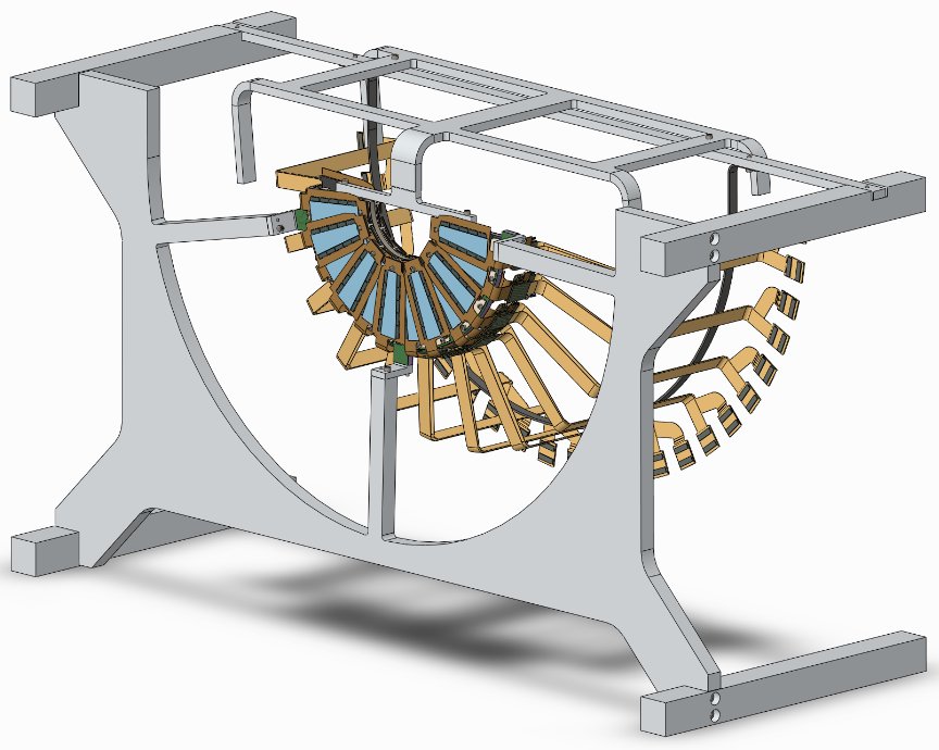
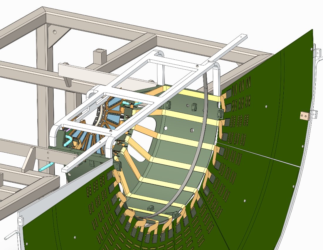
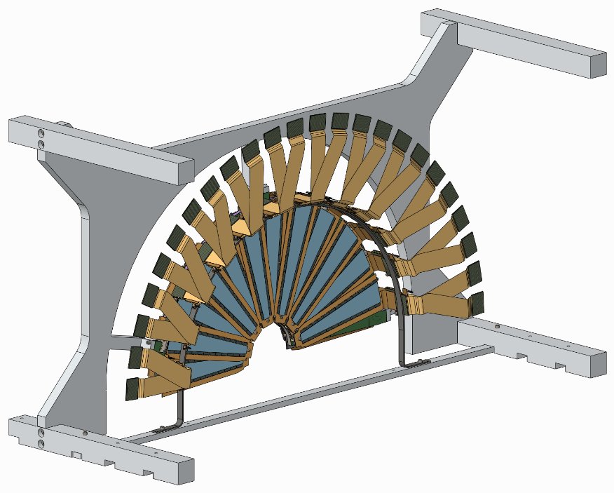
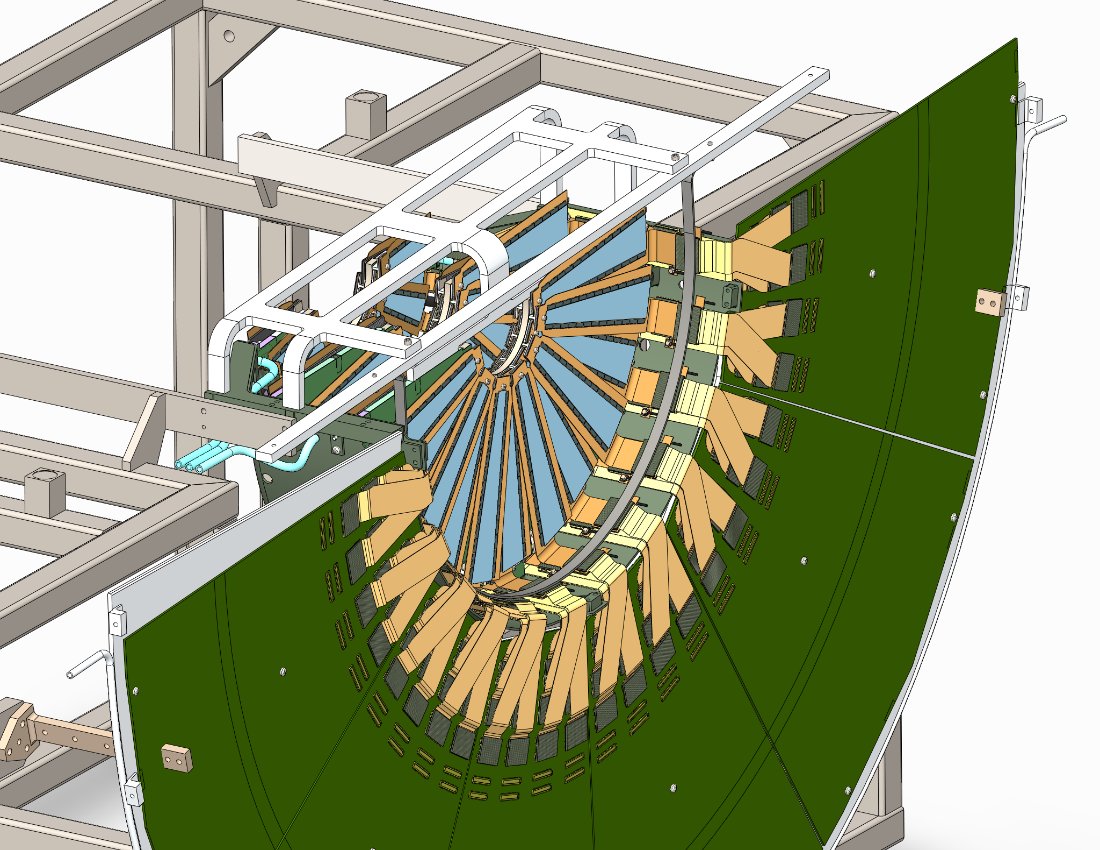
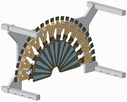
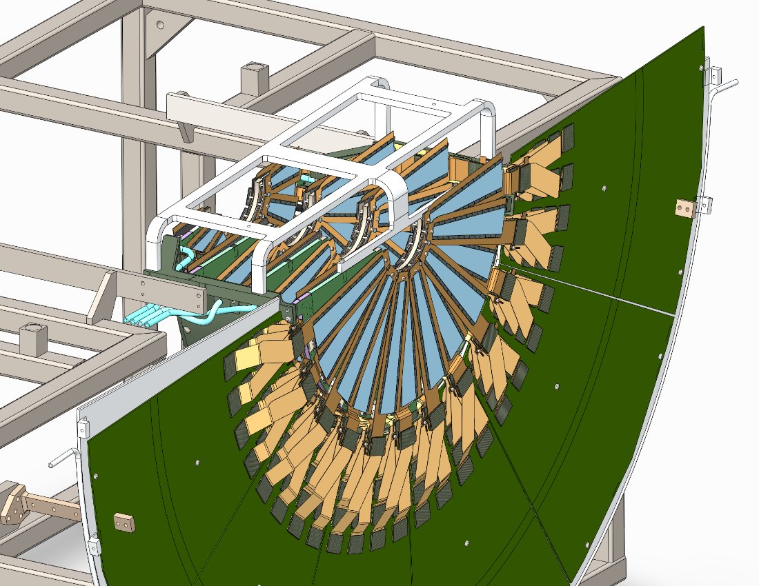
When the assembly is lowered into the Handling and Assembly fixture, the unequal legs come to rest on the edge of the carbon cage, and define the proper rotation angle of station-1. Station 1 can now be attached to the cage.
Cables are now attached to the ROC boards, threads to the carbon arc are cut and the lifting fixture can be removed.

Same procedure for Station 2

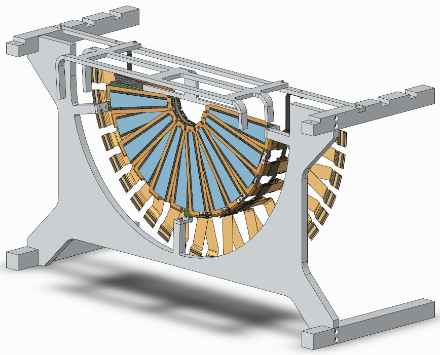
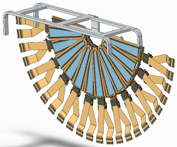
Note that as Station 2 is lowered into the Handling and Assembly fixture, the Station-1 cables (top right in this picture) need to be pushed out by a mm or so in order to let the Station-2 top attachment point pass.
Note that the hoop is actually underneath the HDI connectors - we will do without a hoop for St.3.
jpg, pdf
Same for Station 3.
Push station-1 and 2 cables out of the way of the Station-3 top attachment tab.
Since the Station-4 cables are the least flexible, we can loosen the ROC screws a bit to allow for small movement of the ROC cards if the Station-4 cables need this wiggle room.